RED-1
Remote Ethernet Device 1 (RED-1) is an external remote control panel that integrates with Nexia systems via Ethernet, using a single CAT5 cable for control and Power-over-Ethernet (PoE). RED-1 allows for the selection of up to 32 control items. A control item can be the initiation of a logic event (such as a preset recall or a source selection), selection of a volume assignment, or both. Volume assignments may be individual or ganged levels within the layout, including Level Control blocks, as well as levels within other component blocks (such as Input/Output blocks, Mixers, Equalizers, etc).
|

|
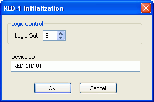
When a RED-1 block is first placed into the layout, an initialization dialog box appears.
Logic Out specifies the number of logic connection points (0 to 32) on the RED-1 block. These connection points are typically wired to Remote Preset or Source Selection blocks but can also be used as general-purpose logic inputs.
Device ID is the name given to each RED-1 block and should correspond to the Device ID of a physical remote panel. No two RED-1 blocks in any layout may have the same Device ID; however, multiple RED-1 panels may have the same Device ID. In that case, the panels’ functions are identical and governed by the RED-1 block with the corresponding Device ID.
|
|

|
RED-1 is represented in the layout as a block with a number of logic connection points (determined by the Logic Out setting when the block is created), plus a DF logic output node, which outputs logic high when at least one like-named RED-1 unit is discovered on the network.
|
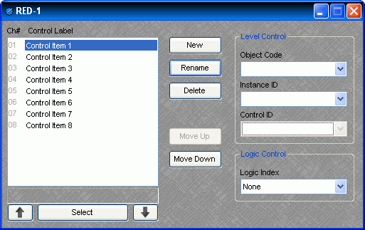
All programmed panel functions are assigned using the control dialog box, which is produced by double-clicking the RED-1 block.

A list displays all defined control items, each with a Channel Number and customizable Control Label. The New button creates a control item in the list, and the user is prompted to either accept the default label or enter a new one. Rename allows the user to change the Control Label of the selected control item. Delete removes the selected control item from the list. Move Up and Move Down modify the order of the control items in the list, giving the user the ability to control the display order of the control items on the RED-1 panel.
Each control item may have a Level Control assignment, a Logic Control assignment, or both.
Level Control
Object Code selects from a list of blocks found in the layout, and the Instance ID is entered automatically, if known. Control ID selects from a list of available levels within the chosen block.
Logic Control
Logic Index specifies which logic connection point, if any, on the RED-1 block will be triggered when that control item is selected.
Once the RED-1 block has been programmed with control items, the Select and Up/Down Arrow buttons at the bottom of the control dialog box may be used to mimic how the control will function from the physical panel.
Control dialog boxes for RED-1 devices may be minimized to create user control surfaces (see Customizing Component Objects).


