Logic Box
|
|
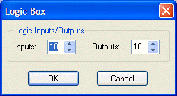
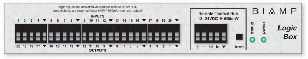
The Logic Box is an external control device, which provides twenty logic input/output connections. When a Logic Box is placed, an Initialization Properties dialog box appears for assigning the quantities of logic inputs/outputs (20 total). Logic inputs allow external switches to initiate NEXIA actions. Actions can be individual or grouped functions within NEXIA. This includes recalling presets, ducking, combining, etc. Logic outputs can be used to control additional equipment, external to NEXIA. |
|
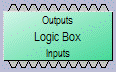
Logic Box components have no Control Dialog Boxes. They are represented in the layout as a block with a total of twenty control input/output nodes. Logic Inputs (on the box) are represented as control output nodes (on the block). These control output nodes may be connected to control input nodes on other components, such as Remote Preset Buttons, Room Combiners, Duckers, Mute Buttons, and Level Inc/Dec controls. Logic Outputs (on the box) are represented as control input nodes (on the block). These control input nodes may be connected to control output nodes on other components, such as Auto Mixers, Duckers, and Select 8. Unlike other components, Logic Box output nodes may be connected to input nodes on the same Logic Box block, allowing Logic Inputs (external switches) to control Logic Outputs (external equipment). |
|
|
Logic Box behavior can be altered using Logic Gates. Please refer to the 'Installation Guide' (included with controls), or see Remote Control Bus for more information. External controls must be identified (see Device Maintenance) and associated with their corresponding component blocks within the layout (see Equipment Table). |
Up to 20 logic inputs are availble on the Logic Box. Logic inputs allow remote control of NEXIA via external circuits such as switches, relays, and logic outputs from other devices. When nothing is connected to a logic input, an internal pull-up resistor keeps it at a 'high' state (+5.0 VDC). The logic input is activated when its input goes 'low' (less than +0.8 VDC), and is de-activated when its input goes 'high' (greater than +2.0 VDC). A logic input can be controlled in one of three ways: 1) Using an 'open-collector' or 'open-drain' logic output from an external device to short the logic input to ground. 2) Using a switch, relay, or other contact-closure to short the logic input to ground. 3) Using an active 5V TTL output driver circuit (such as from a third-party controller) to actively drive the logic input to a 'high' or 'low' state. Multiple contact-closures or 'open-collector'/'open-drain' logic outputs may be wired in parallel to a single logic input (see diagram below). Open-collector or open-drain logic outputs and contact-closures should be rated for at least 5 Volts / 1mA operation. Active output driver circuits should not exceed a signal range of 0~5 Volts DC, and should have a minimum pulse width of 10 milli-seconds. The logic input impedance is approximately 10k ohms.
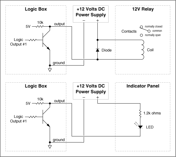
The Logic Box provides up to 20 logic outputs. Logic outputs can be used to control relays and indicators or to drive logic inputs of other devices. The Logic Box logic outputs are 'open collector' with an internal pull-up. Each logic output is an NPN transistor with the collector being the output and the emitter being ground (see diagram below). When a logic output is turned on, the transistor provides a path for DC current to flow, lowering the output voltage to below 0.8V. When a logic output is turned off, the internal pull-up resistor raises the output voltage to near 5V, depending on the output current. To activate external relays or indicators, an external power supply must be used (see diagram below). The logic output transistors are rated up to a maximum of 40 VDC and 500 mA per output (24 volt relay coils maximum). However, +12 Volts DC is sufficient power for most applications. When using the logic outputs to control relays, protection diodes must be used to suppress high voltage transients that are generated when the relays turn off (see diagram below).