Voltage Control Box
|
|
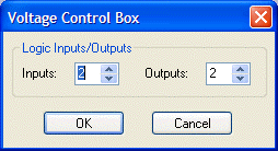
The Voltage Control Box (VCB) is an external control device, which provides four analog potentiometer inputs and four logic inputs/outputs. When a VCB is placed, an Initialization Properties dialog box appears for assigning the quantities of logic inputs/outputs (4 total). Although the quantity of logic connections on a Voltage Control Box (4) is different from those on a Logic Box (20), their operation and behavior are identical. (See Logic Box for further explanation of logic inputs/outputs). |
|

|
|
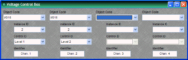
Once a VCB block has been placed, double-clicking it will produce a dialog for assigning Analog (potentiometer) controls. A single VCB allows potentiometer adjustment of up to four selectable Nexia levels. Levels can be individual or ganged levels within Nexia. This includes Level Control blocks, as well as levels within other component blocks (such as Inputs & Outputs, Mixers, Equalizers, etc.). Object Code selects from a list of blocks found in the layout, and Instance ID is entered automatically, but both can be found easily using Object ID Inspector. Control ID selects from a list of available levels within the chosen block. Identifier provides a custom label for the assigned control.
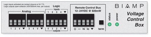
External controls must be identified (see Device Maintenance) and associated with their corresponding component blocks within the layout (see Equipment Table). The VCB will assume a full range of 0~5 Volts returning from connected potentiometers, unless the VCB Calibration procedure is followed (see Device Maintenance). Please refer to the 'Installation Guide' (included with controls), or see Remote Control Bus for more information.