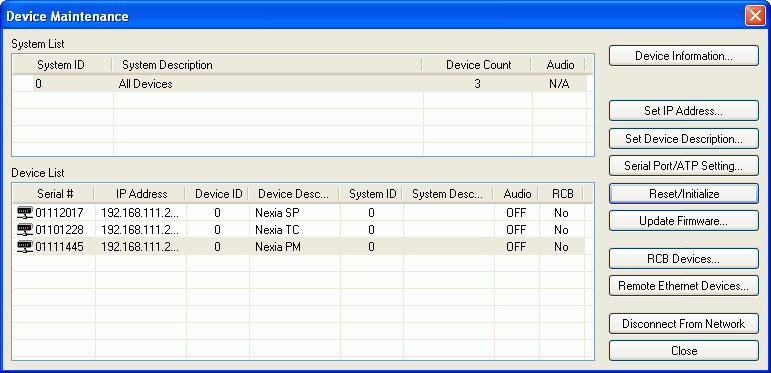

Device Information provides information (such as firmware version, input/output configuration, etc.) regarding the selected device. Set IP Address assigns a device IP Address such as 192.168.1.X (where range of X = 1~254). The factory default IP Address is 192.168.1.101. However, IP Addresses cannot be duplicated, even in simple (NEXIA only) networks, and must be carefully managed when network topology is more complex. Set Device Description allows the selected device to be given a descriptive name. Serial Port Setting selects the baud rate for RS-232 communications (default 38,400) and allows responses to NTP commands to be suppressed. Reset/Initialize clears all current system design data from the selected device. This happens automatically whenever a new system design file (.NEX) is uploaded (see Send Configuration).
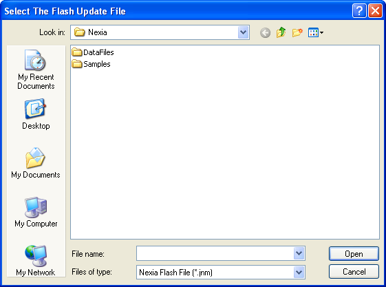
Update Firmware produces a file browser window.

When a valid firmware file is selected, a dialog window is produced that shows all discovered devices in a table with columns indicating System ID, Device IP Address, and other details for each unit. To specify a unit for updating, place a check in that unit’s Update box. Buttons are provided to Select All entries and Clear All entries. Press the Update button to perform the firmware update on the selected units and Cancel to exit this window.

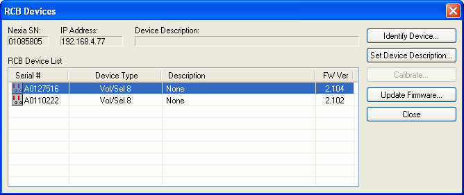
RCB Devices opens a list of devices connected to the Remote Control Bus of the selected NEXIA device. Identify Device causes indicators on the selected device to flash (for physical location). Set Device Description allows the selected device be given a custom name. Calibrate is enabled only if a Voltage Control Box (VCB) is the selected device (see VCB Calibration). Update Firmware allows future firmware updates to be loaded into the selected device. The information in this list (including Serial #) is used to establish proper association between the external physical controls and their corresponding component counterparts in the layout (see Equipment Table).

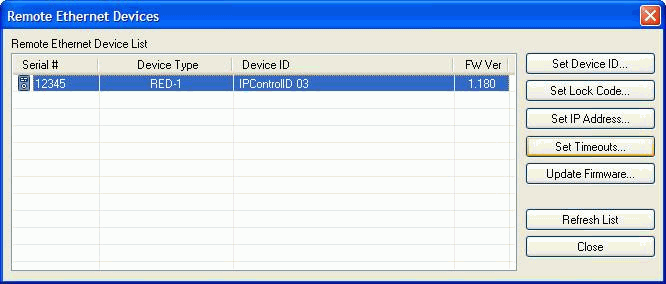
Remote Ethernet Devices opens a list of any NPS-1 or RED-1 remote Ethernet devices connected to the control network of the selected Nexia device.

|
|
Set Device ID allows the selected remote device to be given a name that matches that of the corresponding block in the design layout file.
|
|
|
Set Lock Code allows the selected remote device to be assigned password protection. During normal operation, the user will be prompted for the password before being given control access.
|
|
|
Set IP Address allows the selected remote device to be assigned an IP address. Use the default setting (which allows the device to obtain an IP address automatically from a DHCP server on the network) in most cases, except possibly when adding RED-1 devices to an existing Ethernet network.
|
|
|
When a RED-1 device is selected, the Set Timeouts button becomes active. Set Timeouts allows the Device Lock, LCD Dimmer, and Device Sleep timeouts for the RED-1 to be modified. Update Firmware allows future firmware updates to be loaded into the selected device. The information in the list (including Serial # and Device ID) is used to establish proper association between the external physical devices and their corresponding components in the layout. |
Set Station ID, Set Lock Code, and Set IP Address may instead be assigned during setup of the physical devices themselves (see the Remote Ethernet Device-1 operation manual).