Telephone Interface
The NEXIA TC Telephone Interface provides connection and control via a standard analog telephone line and a desk-set station (see TC Hardware). The Telephone Interface is represented by as many as five separate blocks, as determined during placement into the Layout via the Object Toolbar. Two primary blocks represent the audio Receive and Transmit functions. Three optional control blocks may be added individually at any time, representing functions for Dialer, DTMF Decode, and Control/Status.
|

|
The Receive block provides an output mix of incoming audio and internal ring tone signals. Also, a Hook Switch (HS) control input node allows manual answering of incoming calls, and a Ring indication (RI) control output node provides indication of incoming calls. |
|
|
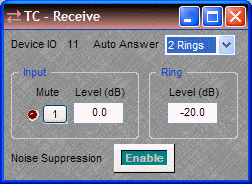
Double-clicking the Receive block produces a control dialog box.
Device IO indicates which hardware connection is associated with that software block. Auto Answer selects the number of rings (or OFF) for automatic answering of incoming calls. Input provides level adjustment and muting of incoming audio signals. Ring provides level adjustment of the internal ring tone signals for incoming calls. Noise Suppression enables cancellation of telephone line noise. |
|

|
The Transmit block provides an input connection for outgoing audio signals. |
|
|
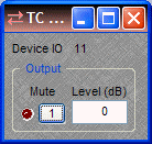
Double-clicking the Transmit block produces a control dialog box.
Device IO indicates which hardware connection is associated with that software block. Output provides level adjustment and muting of outgoing audio signals. |
|

|
The Dialer block provides several control input nodes: nodes 1~16 trigger corresponding speed-dial numbers; Rdl triggers redial of last number; HF triggers hook flash; and DM selects pulse dial mode (not currently supported). A control output node (D) provides indication of dialing in progress. |
|
Double-clicking the Dialer block produces a control dialog box.
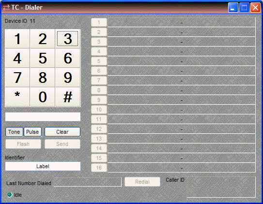
Device IO indicates which hardware input is associated with that software channel. Keypad (1~#) allows number entry via computer mouse. A text box below the Keypad displays the number entry, and allows number entry via computer keyboard ("," = pause). Clear deletes the current number. Send dials the current number and becomes End for terminating the call. Tone/Pulse selects the dialing mode. Flash produces a hook flash on an active line. Identifier allows custom labeling for line identification. Last Number Dialed displays the number for the previous outgoing call. Redial dials Last Number Dialed. Caller ID displays the number from the current (or last) incoming call. Idle changes to indicate call progress, while the adjacent LED indicates an active line. Buttons 1~16 initiate speed-dialing. |
|
|
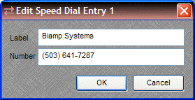
Right-clicking over buttons 1~16 provides a dialog box for entering speed-dial numbers and labeling. Double-clicking over a previous entry will allow editing.
A Dialer control dialog box can be minimized to create a user control surface (see Customizing Component Objects). |
|

|
The DTMF Decode block provides several control output nodes: nodes 1~D provide indication of corresponding DTMF tones; Any provides indication of any tones. |
|

|
Double-clicking the DTMF Decode block produces a control dialog box. Device IO indicates which hardware connection is associated with that software block. DTMF Decode enables decoding. Decoded Data displays the characters associated with the tones. |
|

|
The Control/Status block provides several control output nodes: HS indicates hook switch OFF condition; DTD indicates dial tone detected; BTD indicates busy tone detected; RTD indicates ring tone detected; LR indicates line ready (connected); LIU indicates line in use (by other extension); LI indicates line intrusion (by other extension); LF indicates line fault condition (may require service). |
|
|
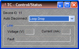
Double-clicking the Control/Status block produces a control dialog box. Device IO indicates which hardware connection is associated with that software block. Auto Disconnect provides three methods of call termination (the method used depends on the far-end equipment). Loop Drop detects interruptions in the current of the telephone circuit, Call Progress detects a special tone indicating call termination, and some far-end equipment may use a combination of Loop Drop + Call Progress. NOTE: Auto Disconnect reliability may be affected by intermittent line interruptions or cellular calls. Line displays voltage, current, and fault conditions on the line. |
NOTES: Before compiling, a Country must be designated in the Receive block Property Sheet. For protection of privacy, the Last Number Dialed and Caller ID displays (on the Dialer control dialog box) can be disabled via the Control/Status block Property Sheet. Sidetone Level can be set via the Dialer block Property Sheet.


